
Network architecture within modern enterprise environments demands high availability; however, the physical redundancy required to ensure uptime often introduces the risk of catastrophic Layer 2 loops. The STP Spanning Tree protocol serves as the primary defense mechanism against these loops, which occur when multiple active paths exist between switches. Without a loop-prevention algorithm, broadcast frames circulate infinitely, consuming all available bandwidth and causing a broadcast storm. This leads to total network collapse, high packet-loss, and the eventual failure of connected applications such as industrial logic-controllers or cloud-based database clusters. STP functions by logically disabling redundant paths, effectively creating a loop-free tree topology while maintaining a standby link for failover. In the event of a primary link failure, the protocol recalculates the topology and re-enables the blocked port, ensuring continuous data flow with minimal signal-attenuation. This manual provides the technical framework for implementing, managing, and hardening STP Spanning Tree across high-density infrastructure.
Technical Specifications
| Requirement | Default Port/Operating Range | Protocol/Standard | Impact Level (1-10) | Recommended Resources |
| :— | :— | :— | :— | :— |
| Managed Switch | Bridge ID (0-61440) | IEEE 802.1D | 10 | 128MB RAM / 400MHz CPU |
| Rapid STP | Port Cost (1-200,000,000) | IEEE 802.1w | 10 | 256MB RAM / 800MHz CPU |
| Multiple STP | Instance ID (0-4094) | IEEE 802.1s | 9 | 512MB RAM / 1GHz+ CPU |
| BPDU Handling | Destination MAC: 01:80:C2:00:00:00 | Encapsulated LLC | 10 | Minimal CPU Overhead |
| Fiber Links | 1Gbps to 100Gbps | SFP/QSFP Standards | 8 | Material Grade: OM4/OS2 |
The Configuration Protocol
Environment Prerequisites:
Implementation requires managed switches supporting the IEEE 802.1w (RSTP) or IEEE 802.1s (MST) standards. All physical cabling must be verified for signal integrity using a fluke-multimeter or equivalent optical power meter to prevent unidirectional link failures. Administrative access (Privileged EXEC mode or sudo equivalent) is mandatory for modifying the Bridge ID and port priorities. If deploying in a virtualized environment, ensure the hypervisor virtual switch supports BPDU Transparency or is configured to participate in the STP domain to avoid encapsulation errors.
Section A: Implementation Logic:
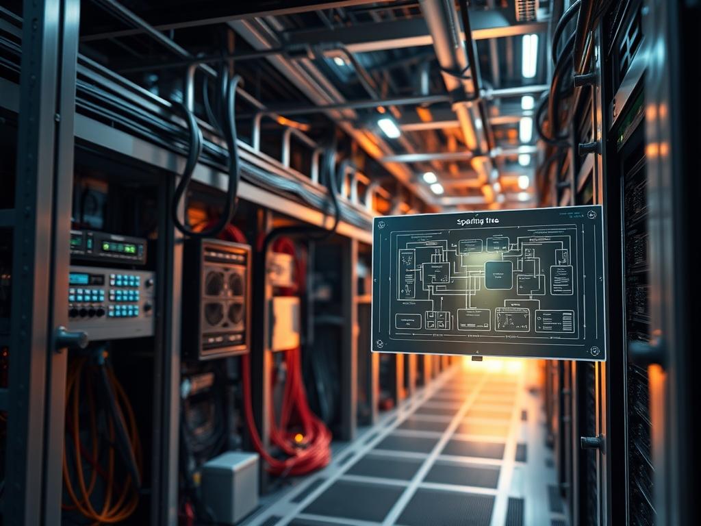
The logic of STP Spanning Tree is centered on the election of a Root Bridge, which serves as the reference point for the entire network. The election is based on the Bridge ID, a 64-bit value composed of a configurable Priority and the switch’s base MAC address. The switch with the lowest Bridge ID becomes the Root Bridge. Every other switch (Non-Root Bridges) determines the shortest path to the Root based on the cumulative link cost, known as the Root Path Cost. Ports are then transitioned into specific roles: Root Ports (the best path to the Root), Designated Ports (the path toward the segments), and Alternate/Backup Ports (the blocked redundant paths). By utilizing Rapid Spanning Tree (802.1w), the network achieves faster convergence via a “proposal-agreement” handshake rather than relying on the legacy timers used in 802.1D. This ensures that the state transition remains idempotent and limits the period of packet-loss during topology changes.
Step-By-Step Execution
1. Global Spanning Tree Activation
To begin, verify the current STP state and enable the protocol globally.
Command: spanning-tree mode rapid-pvst
System Note: This command interacts with the switch kernel to initialize the Rapid Per-VLAN Spanning Tree process. It changes the state machine from the 802.1D standard to 802.1w, improving convergence throughput by eliminating the 15-second listening and learning delays.
2. Manual Root Bridge Assignment
Force the election of a specific switch as the Root Bridge by lowering its priority.
Command: spanning-tree vlan 10 priority 4096
System Note: By decreasing the Bridge ID priority from the default 32768 to 4096, the administrator manually dictates the center of the tree. This prevents random MAC-based election, which could otherwise place the Root Bridge on an underpowered edge switch, increasing overall network latency.
3. Edge Port Optimization
Enable PortFast on host-facing interfaces where no switches are connected.
Command: spanning-tree portfast or spanning-tree portfast edge
System Note: This command instructs the switch logic to skip the STP state machine for that specific physical port. As soon as a link-up signal is detected, the port transitions immediately to a forwarding state. This prevents DHCP timeouts for connected PCs or logic-controllers.
4. BPDU Guard Activation
Protect the edge ports from accidental switch loops or unauthorized bridge insertion.
Command: spanning-tree bpduguard enable
System Note: This security logic monitors the interface for Bridge Protocol Data Units. If a BPDU is received on a PortFast-enabled interface, the switch kernel triggers an “err-disable” state, physically shutting down the port to prevent a loop. This handles the concurrency of user-endpoint connections without compromising the core stability.
5. Verification and Path Analysis
Audit the resulting topology to ensure the desired paths are active.
Command: show spanning-tree vlan 10
System Note: This utility pulls data from the volatile Bridge Information Base (BIB). It displays the Root Bridge MAC, the local Bridge ID, and the status of every port (Forwarding, Blocking, or Learning). It is the primary tool for validating that the physical asset reflects the architectural design.
Section B: Dependency Fault-Lines:
Common failures in STP deployment often stem from version mismatches. If one switch is running legacy 802.1D while others use 802.1w, the entire network reverts to legacy timers to maintain backward compatibility, significantly increasing convergence latency. Another critical fault-line is unidirectional links, where a fiber strand fails in one direction; the switch may stop receiving BPDUs but continue to send data, leading to a loop. To mitigate this, Unidirectional Link Detection (UDLD) must be used in conjunction with STP. Furthermore, incorrect VLAN pruning on trunk links can lead to “STP Instance Exhaustion,” where the switch runs out of CPU resources to calculate spanning trees for thousands of individual VLANs.
THE TROUBLESHOOTING MATRIX
Section C: Logs & Debugging:
When a loop occurs, CPU utilization on the management plane typically spikes to 100 percent, and the console may become unresponsive. The primary visual cue is the rapid, synchronous flashing of all link lights on a switch chassis.
1. Error Code: %SPANTREE-2-BLOCK_PVID_LOCAL:
Cause: This indicates a PVLAN ID mismatch on a trunk link.
Resolution: Inspect the allowed VLAN list on both ends of the trunk using show interfaces trunk; ensure native VLANs match to prevent payload leakage between VLANs.
2. Error Code: %SPANTREE-2-ROOTGUARD_BLOCK:
Cause: A port configured with Root Guard received a superior BPDU, meaning another switch is attempting to become the Root Bridge.
Resolution: Use show spanning-tree inconsistentports to identify the rogue switch. Verify if a new physical asset was added to the infrastructure without proper configuration.
3. Log Entry: %SYS-5-CONFIG_I: Configured from console by root:
Action: Cross-reference configuration changes with the timestamp of network instability. If an idempotent change was applied incorrectly, roll back to the previous startup-config using the copy startup-config running-config command.
OPTIMIZATION & HARDENING
Performance Tuning:
To minimize latency and maximize throughput, adjust the STP path cost for high-speed links. While STP automatically assigns costs based on bandwidth, manual overrides can force traffic over preferred fiber paths. Use the command spanning-tree vlan [ID] cost [value] to influence the steering logic. Modern 10Gbps and 40Gbps links should use the 32-bit “long” cost values to provide more granular control over complex topologies, ensuring that high-throughput segments are prioritized over legacy 1Gbps copper connections.
Security Hardening:
Beyond BPDU Guard, administrators must implement Root Guard on all ports pointing toward downstream switches. This prevents an unauthorized or misconfigured switch from seizing the Root Bridge role. Additionally, enabling Loop Guard on non-designated ports provides an extra layer of protection against hardware failure; if BPDUs stop arriving on a blocking port due to a hardware glitch, Loop Guard keeps the port in a “loop-inconsistent” state rather than transitioning it to forwarding. This prevents the emergence of a loop if the physical signal-attenuation creates a “black hole” for control traffic.
Scaling Logic:
In environments with thousands of VLANs, the overhead of running a separate STP instance for every VLAN (PVST+) becomes prohibitive for switch CPU resources. To maintain stability, transition to Multiple Spanning Tree (MSTP). MSTP maps multiple VLANs to a single spanning tree instance, significantly reducing the control plane overhead. Configuration requires defining an MST region, revision number, and instance map across all participating switches. This allows for high-concurrency data processing while keeping the STP heartbeat traffic at a manageable level.
THE ADMIN DESK
How do I identify which switch is the Root Bridge?
Execute the command show spanning-tree root on any switch. The output provides the Bridge ID of the Root. If the local switch is the Root, the system note will state “This bridge is the root” for the specified VLAN.
What happens if I connect two ports on the same switch?
The STP algorithm detects the loop through the Bridge Protocol Data Units. It will identify that it is receiving its own BPDUs and will immediately place one of the ports into a Blocking state to prevent a broadcast storm.
Why is my port stuck in the Learning state?
This typically occurs in legacy 802.1D STP. The port is waiting for the forward-delay timer to expire to ensure no loops exist before forwarding data. Upgrading the switch environment to Rapid STP (802.1w) will eliminate this prolonged delay.
Can STP protect against loops in a virtual switch?
Virtual switches often do not run STP but will pass BPDUs. To prevent loops, configure the physical switch ports connected to the hypervisor with BPDU Guard or ensure the virtual environment has its own loop-prevention logic enabled (e.g., MAC learning limits).
Is Spanning Tree necessary if I use Port Channels?
Yes. While Port Channels (LACP) aggregate multiple physical links into one logical link to prevent loops between those specific wires, STP is still required to manage overall topology redundancy and prevent loops across different logical paths or switches.